| Fw 190 |
|---|
|
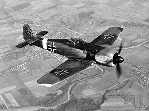
| Captured Fw 190 A in replicated Luftwaffe insignia. |
| Role | Fighter |
|---|
| Manufacturer | Primarily Focke-Wulf Flugzeugbau AG, but also AGO, Arado, Fieseler, Mimetall, Norddeutsche Dornier and others |
|---|
| Designer | Kurt Tank |
|---|
| First flight | 1 June 1939 |
|---|
| Introduction | August 1941 |
|---|
| Retired | 1945 (Luftwaffe); 1949 (Turkey) |
|---|
| Primary users | Luftwaffe
Hungarian Air Force
Turkish Air Force |
|---|
| Produced | 1941–45; 1996: 16 reproductions |
|---|
| Number built | Over 20,000 |
|---|
| Variants | Ta 152 |
|---|
The
Focke-Wulf Fw 190 Würger (English: Shrike) was a German single-seat, single-engine fighter aircraft designed by Kurt Tank in the late 1930s and widely used during World War II. Powered by a radial engine, the 190 had ample power and was able to lift larger loads than its well-known counterpart, the Messerschmitt Bf 109. The 190 was used by the Luftwaffe in a wide variety of roles, including day fighter, fighter-bomber, ground-attack aircraft and, to a lesser degree, night fighter.
When the Fw 190 started flying operationally over France in August 1941, it quickly proved itself to be superior in all but turn radius to the Royal Air Force's main front-line fighter, the Spitfire Mk. V.
[1] The 190 wrested air superiority away from the RAF until the introduction of the vastly improved Spitfire Mk. IX in July 1942 restored qualitative parity.
[2] The Fw 190 made its air combat debut on the Eastern Front in November/December 1942; though Soviet pilots considered the Bf 109 the greater threat, the Fw 190 made a significant impact. The fighter and its pilots proved just as capable as the Bf 109 in aerial combat, and in the opinion of German pilots who flew both, provided increased firepower and manoeuvrability at low to medium altitude.
The Fw 190 became the backbone of the
Jagdwaffe (Fighter Force), along with the Bf 109. On the Eastern Front, the Fw 190 was versatile enough to use in
Schlachtgeschwader (Battle Wings or Strike Wings), specialised ground attack units which achieved much success against Soviet ground forces. As an interceptor, the Fw 190 underwent improvements to make it effective at high altitude, enabling it to maintain relative parity with its Allied opponents. The Fw 190A series' performance decreased at high altitudes (usually 6,000 m (20,000 ft) and above), which reduced its effectiveness as a high-altitude interceptor, but this problem was mostly rectified in later models, particularly in the Junkers Jumo 213 inline-engine Focke-Wulf Fw 190D series, which was introduced in September 1944. In spite of its successes, it never entirely replaced the Bf 109.
The Fw 190 was well liked by its pilots. Some of the Luftwaffe's most successful fighter aces claimed a great many of their kills while flying it, including Otto Kittel, Walter Nowotny and Erich Rudorffer.
Contents
- 1 Early development
- 2 Fw 190 A
- 3 High-altitude developments
- 4 Fw 190D
- 5 Ground attack variants
- 6 Trainer versions
- 7 Combat history
- 8 Survivors and modern builds/reproductions
- 9 Production
- 10 Operators
- 11 Specifications (Fw 190 A-8)
- 12 Specifications (Fw 190 D-9)
- 13 See also
- 14 References
- 15 External links
Early development
Genesis
In autumn 1937, the
German Ministry of Aviation asked various designers for a new fighter to fight alongside the
Messerschmitt Bf 109, Germany's front line fighter. Although the Bf 109 was an extremely competitive fighter, the Ministry of Aviation was worried that future foreign designs might outclass it, and wanted to have new aircraft under development to meet these possible challenges.
[3]Kurt Tank responded with a number of designs, most incorporating liquid-cooled inline engines. However, it was not until a design was presented using the air-cooled, 14-cylinder
BMW 139
radial engine that the Ministry of Aviation's interest was aroused. As this design used a radial engine, it would not compete with the inline-powered Bf 109 for engines, when there were already too few
DB 601's to go around.
[4] This was not the case for competing advanced designs like the
Heinkel He 100 or
Focke-Wulf Fw 187, where production would compete with the 109 or
Messerschmitt Bf 110 for engine supplies. After the war, Tank denied a rumour that he had to "fight a battle" with the Ministry to convince them of the radial engine's merits.
[5]Design concepts
At the time, the use of radial engines in land-based fighters was relatively rare in Europe, as it was believed that their large frontal area would cause too much drag on something as small as a fighter. Tank was not convinced of this, having witnessed the successful use of radial engines by the
US Navy, and felt a properly
streamlined installation would eliminate this problem.
[4]The hottest point on any air-cooled engine are the cylinder heads, located along the outside diameter of a
radial engine. In order to provide sufficient air to cool the engine, airflow had to be maximized at this outer edge, which was normally accomplished by leaving majority of the front face of the engine being left open to the air. During the late 1920s,
NACA led development of a dramatic improvement by placing an
airfoil-shaped ring around the outside of the cylinder heads (the
NACA cowling). The shaping accelerated the air as it entered the front of the cowl, increasing the total airflow, and allowing the opening in front of the engine to be made smaller.
[6]Tank introduced a further refinement to this basic concept. He suggested placing most of the airflow components on the propeller itself, in the form of a oversized
propeller spinner whose outside diameter was the same as the engine itself. The cowl around the engine proper was greatly simplified, essentially a basic cylinder. Air entered through a small hole at the center of the propeller, and was directed through ductwork in the spinner so it was blowing rearward along the cylinder heads. To provide enough airflow, a cone was placed in the center of the hole, over the propeller hub, which was intended to compress the airflow and allow a smaller opening to be used. In theory, the tight-fitting cowling also provided some thrust due to the compression and heating of air as it flowed through the cowling.
[7]As to the rest of the design philosophy, Tank wanted something more than an aircraft built only for speed. Tank outlined the reasoning:
The Messerschmitt 109 [
sic] and the British Spitfire, the two fastest fighters in world at the time we began work on the Fw 190, could both be summed up as a very large engine on the front of the smallest possible airframe; in each case armament had been added almost as an afterthought. These designs, both of which admittedly proved successful, could be likened to racehorses: given the right amount of pampering and easy course, they could outrun anything. But the moment the going became tough they were liable to falter. During World War I, I served in the cavalry and in the infantry. I had seen the harsh conditions under which military equipment had to work in wartime. I felt sure that a quite different breed of fighter would also have a place in any future conflict: one that could operate from ill-prepared front-line airfields; one that could be flown and maintained by men who had received only short training; and one that could absorb a reasonable amount of battle damage and still get back. This was the background thinking behind the Focke-Wulf 190; it was not to be a racehorse but a
Dienstpferd, a cavalry horse.
[8]
One of the main features of the Fw 190 was its wide-tracked, inwards-retracting landing gear. Tank appreciated that operating from primitive airfields in wartime would require a stable undercarriage — a lesson learned from witnessing the difficulty of moving machinery in the First World War. The wide-track landing gear spacing gave it better ground handling characteristics, and it suffered fewer ground accidents than the Bf 109 with its narrow-track landing gear. The undercarriage was designed to withstand a sink rate of 15 feet per second (4.5 meters per second, 900 feet per minute), double the strength factor usually required. Hydraulic wheel brakes were used.
[9]Most aircraft of the era used cables and pulleys to operate their controls. The cables tended to stretch, resulting in the sensations of "give" and "play" that made the controls less crisp and responsive, and required constant maintenance to correct. For the new design, the team replaced the cables with rigid pushrods and bearings to eliminate this problem.
[N 1] Another innovation was making the controls as light as possible. The maximum resistance of the ailerons was limited to eight pounds, as the average man's wrist could not exert a greater force. The
empennage (tail assembly) featured relatively small and well-balanced horizontal and vertical surfaces.
[10]The design team also attempted to minimize changes in the aircraft's trim at varying speeds, thus reducing the pilot's workload. They were so successful in this regard that they found in-flight-adjustable aileron and rudder trim tabs were not necessary. Small, fixed tabs were fitted to control surfaces and adjusted for proper balance during initial test flights. Only the elevator trim needed to be adjusted in flight (a feature common to all aircraft). This was accomplished by tilting the entire horizontal tailplane by an electric motor, with an angle of incidence ranging from -3° to +5°.
[11]Another aspect of the new design was the extensive use of electrically powered equipment instead of the hydraulic systems used by most aircraft manufacturers of the time. On the first two prototypes, the main landing gear was hydraulic. Starting with the third prototype, the undercarriage was operated by push buttons controlling electric motors in the wings, and was kept in position by electric up and down-locks.
[12] The armament was also loaded and fired electrically. Tank believed that service use would prove that electrically powered systems were more reliable and more rugged than hydraulics, electric lines being much less prone to damage from enemy fire.
[10]As was the case for the 109, the 190 featured a fairly small wing planform with relatively high
wing loading. This presents a trade-off in performance; an aircraft with a smaller wing suffers less
drag in most flight and therefore flies faster and may have better range. However, it also means the wing cannot generate
extra lift as easily, which is needed for maneuvering or flight at high altitudes.The wings spanned 9.5 m (31 ft 2 in) and had an area of 15 m² (161 ft²). The wing was designed using the NACA 23015.3 airfoil at the root and the NACA 23009 airfoil at the tip.
[13]Earlier designs generally featured canopies consisting of small plates of
perspex in a metal framework, and the fuselage running horizontally back from the top of the canopy frame. This design considerably limited visibility, especially to the rear. The introduction of
vacuum forming led to the creation of the "bubble canopy" which was largely self-supporting, and could be mounted above the fuselage, offering greatly improved all-round views. Tank's new design included such a design that used only a single frame where the front and rear sections met, just in front of the pilot.
First prototypes
Fw 190 V1 in its original form with the streamlined engine cowling and ducted spinner. The pointed tip of the internal spinner can also be seen. Pilot is probably Hans Sander.
The first prototype, the
Fw 190 V1 (civil registration
D-OPZE), powered by a 1,550
PS (1,529 hp, 1,140 kW)
BMW 139 14-cylinder two-row radial engine, first flew on 1 June 1939. It soon showed exceptional qualities for such a comparatively small aircraft, with excellent handling, good visibility and speed (initially around 610 km/h (380 mph)).
[14] The roll rate was 162° per second at 410 km/h (255 mph), but the aircraft had a high stall speed of 205 km/h (127 mph).
The cockpit, located directly behind the engine, quickly became uncomfortably hot. During the first flight, the temperature reached 55 °C (131 °F), after which Focke Wulf's chief test pilot, Hans Sander commented, "It was like sitting with both feet in the fireplace."
[15] Flight tests soon showed that the expected benefits of Tank's cooling design did not materialize, so after the first few flights, this arrangement was replaced by a smaller, more conventional spinner that covered only the hub of the three-blade VDM propeller.
In an attempt to increase airflow over the tightly cowled engine, a 10-blade fan was fitted at the front opening of the redesigned cowling and was geared to be driven at 3.12 times faster than the propeller shaft's speed. This quickly became standard on the Fw 190 and nearly all other German aircraft powered by the BMW 801.
[16] In this form the V1 first flew on 1 December 1939, having been repainted with the Luftwaffe's
Balkenkreuz and with the
Stammkennzeichen (factory code).
[17] RM+CA.
[18]The Fw 190 V2, designated with the
Stammkennzeichen alphabetic ID code of
FL+OZ (later RM+CB) first flew on 31 October 1939 and was equipped from the outset with the new spinner and cooling fan. It was armed with one
Rheinmetall-Borsig 7.92 mm (.312 in)
MG 17 machine gun and one 13 mm (.51 in) synchronized
MG 131 machine gun in each wing root.
[18]Later prototypes, BMW 801

Fw 190 V5k. This is the V5 with the original small wing. The 12-blade cooling fan and redesigned undercarriage and canopy fairings are visible.
Even before the first flight of the Fw 190 V1, BMW was bench testing a larger, more powerful 14-cylinder two-row radial engine, the
BMW 801. This engine introduced a pioneering example of an
engine management system called the
Kommandogerät (command-device): in effect, an electro-mechanical computer which set mixture, propeller pitch (for the
constant speed propeller), boost, and
magneto timing. This reduced the pilot's work load to moving the throttle control only, with the rest of the associated inputs handled by the Kommandogerät. The drawback was slight and minor surges that made the Fw 190 harder to fly in close formations.
[19] Tank asserted the device did not work well. One of the faults in the system was the violent switching in of the high gear of the supercharger as the aircraft climbed. During a test flight, Tank carried out a loop at medium altitude. Just as he was nearing the top of the loop, at 2,650 m (8,700 ft), the supercharger's high gear kicked in with a jerk. The Fw 190 was on its back, with little airspeed. The sudden change in torque hurled the aircraft into a spin. Tank's
artificial horizon toppled (the cause is not explained). Although Tank did not know whether he was in an upright or inverted spin, he managed to recover after a loss of altitude. The rough transition was smoothed out and the supercharger's gear-change could engage without incident.
[20]The
RLM convinced Focke-Wulf and BMW to abandon the 139 engine in favour of the new engine. The BMW 801 engine was similar in diameter to the 139, although it was heavier and longer by a considerable margin. This required Tank to redesign the Fw 190, resulted in the abandonment of the V3 and V4. The V5 became the first prototype with the new engine, being fitted with the 1,560 PS (1,539 hp, 1,147 kW) BMW 801 C-0. Much of the airframe was strengthened and the cockpit was moved back in the fuselage, which reduced the troubles with high temperatures and for the first time provided space for nose armament. It also reduced visibility in nose-high attitudes, notably when taxiing on the ground.
A 12-blade cooling fan replaced the earlier 10-blade unit, and was likewise installed in front of the engine's
reduction gear housing, still running with the original 3.12:1 reduction ratio, which was standardised for BMW-powered Fw 190s. The
propeller shaft passed through the fan's central plate, which was made of
cast magnesium. The fan provided cooling air not only for the engine cylinders' fins, but also for the annular oil cooler, which was located in the forward part of the cowling. The oil cooler was protected by an armoured ring which made up the front face of the cowling.
[18] A small hole in the centre of the spinner also directed airflow to ancillary components.
[21] Even with the new engine and the cooling fan, the 801 suffered from high rear-row cylinder head temperatures, which in at least one case resulted in the detonation of the fuselage-mounted MG 17 ammunition.
The vertical tail shape was also changed and the
rudder tab was replaced by a metal trim strip adjustable only on the ground. New, stiffer undercarriage struts were introduced, along with larger diameter wheels. The retraction mechanism was changed from hydraulic to electrically powered, which became a hallmark of later Focke-Wulf aircraft system designs, and new
fairings of a simplified design were fitted to the legs.
[18] Another minor change was that the rearmost sections of the sliding
canopy were redesigned by replacing the
plexiglas glazing with
duralumin panels. As this section was behind the pilot's seat, there was little visibility lost.
At first, the V5 used the same wings as the first two prototypes, but to allow for the larger tyres, the wheelwells were enlarged by moving forward part of the
leading edge of the wing root; the wing area became 15.0 m² (161 ft²). The V5 first flew in the early spring of 1940. The weight increase with all of the modifications was substantial, about 635 kg (1,400 lb), leading to higher
wing loading and a deterioration in handling. Plans were made to create a new wing with more area to address these issues. In its original form, this prototype was called the
V5k for
kleine Fläche (small surface).
[22]In August 1940 a collision with a ground vehicle damaged the V5 and it was sent back to the factory for major repairs. This was an opportune time to rebuild it with a new wing which was less tapered in plan than the original design, extending the leading and trailing edges outward to increase the area. The new wing had an area of 18.30 m² (197 ft²), and now spanned 10.506 m (34 ft 5 in). After conversion, the aircraft was called the
V5g for
große Fläche (large surface). Although it was 10 km/h (6 mph) slower than when fitted with the small wing,
V5g was much more manoeuvrable and had a faster climb rate.
[22] This new wing platform was to be used for all major production versions of the Fw 190.
[18]Pre-production, Fw 190 A-0
Fw 190 A-0 were the pre-production series ordered in November 1940, with a total of 28 were built. Because they were built before the new wing design was fully tested and approved, the first nine A-0s had small wings. All were armed with a total of six .30 calibre-class machine guns — two
synchronised 7.92 mm (.312 in)
MG 17 machine guns mounted in the forward fuselage, one similarly synchronized MG 17 in each wing root, and one MG 17 in each of the outboard wings. They were different from later A-series Fw 190s: they had shorter spinners, the
armoured cowling ring was a different shape, with a scalloped hinge on the upper, forward edge of the upper engine cowling, and the bulges covering the interior air intakes on the engine cowlings were symmetrical "teardrops". Also, the panels aft of the exhaust pipes had no cooling slots. Several of these aircraft were later modified for testing engines and special equipment.
[18]The first unit to be equipped with the A-0 was
Erprobungsstaffel 190, formed in March 1941 to help iron out any technical problems and approve the new fighter before it would be accepted for full operational service in mainstream Luftwaffe
Jagdgeschwader. At first, this unit, commanded by Oblt. Otto Behrens, was based at the Luftwaffe's central
Erprobungsstelle facility at
Rechlin, but it was soon moved to
Le Bourget. Engine problems plagued the 190 for much of its early development, and the entire project was threatened several times with a complete shutdown. Had it not been for the input of Behrens and
Karl Borris, both of whom had originally enlisted in the Luftwaffe as mechanics, the Fw 190 program might have died before reaching the front lines. Both men indicated that the Fw 190's outstanding qualities outweighed its deficiencies during several Ministry of Aviation commissions that wished to terminate the program.
[23] Some 50 modifications were required before the Ministry of Aviation approved the Fw 190 for deployment to Luftwaffe units.
[23]Fw 190 A
A-1
Fw 190A, another view of the captured aircraft in the heading's photo. As the aircraft was under USAAF test after repainting, the
Balkenkreuz and swastika are of incorrect size and proportions.

Side-view of Fw 190 A-2 resp. A-3. Compared to the A-0 diagram above the two are similar, the notable change being the addition of the cooling slits on the engine cowling visible just in front of the wing.
The
Fw 190 A-1 rolled off the assembly lines in June 1941. The first few models were shipped to the
Erprobungsstaffel (formerly from II./JG 26
Schlageter) for further testing. Following this testing, the Fw 190 A-1 entered service with II./JG 26, stationed near Paris, France. The A-1 was equipped with the BMW 801 C-1 engine, rated at 1,560 PS (1,539 hp, 1,147 kW) for take-off. Armament consisted of two fuselage-mounted 7.92 mm (.312 in) MG 17s, two wing root-mounted 7.92 mm (.312 in) MG 17s - with all four MG 17s synchronized to fire through the propeller arc - and two outboard wing-mounted 20 mm
MG FF/Ms.
[24] The new longer propeller spinner and the cowling bulges, which became asymmetrical "teardrops" in shape, remained the same for the rest of the A-series. The panel immediately behind the exhaust outlets was unslotted, although some A-1s were retrofitted with cooling slots. A new hood jettisoning system, operated by an MG FF cartridge, was introduced. The pilot's head armour changed in shape and was supported by two thin metal struts in a "V" shape attached to the canopy sides.
[24] The standard radio fitted was the
FuG 7, although some A-1s were also equipped with
FuG 25 "Erstling" IFF (
identification friend or foe) equipment.
[24] The A-1 models still suffered from the overheating that prototype Fw 190s had experienced during testing. After only 30–40 hours of use (sometimes less), many of these early engines had to be replaced.
[25] Focke-Wulf completed 102 A-1s at the
Bremen and
Marienburg factories between June and October 1941. Also in October, a further order of 315 A-1s, subcontracted to
AGO Flugzeugwerke at its
Oschersleben factory, began to be built as A-2s.
[24]A-2
The introduction of the BMW 801 C-2 resulted in the
Fw 190 A-2 model, first introduced in October 1941. As part of this upgrade, a modification to the exhaust system devised by III./JG 26's Technical Officer ("T.O.") Rolf Schrödeter was added. There were 13 exhausts for the 14 cylinders; eight of these were grouped to exit, four on each side, along the forward fuselage, just above the leading edge of the wing; under the forward centre section, between the undercarriage bays were five exhaust stacks, with cylinders 9 and 10 sharing a common pipe.
[26] To quickly implement the fix, it was found that the re-routing could be done easily in
Gruppe workshops. The reduction in temperature affecting the bottom cylinder went a long way to solving the problem.
[27][28] The addition of new ventilation slots on the side of the fuselage further aided cooling, and with the widespread availability of the A-2 in the spring of 1942, the overheating problems were greatly reduced.
The A-2 wing weaponry was updated, with the two wing root-mounted 7.92 mm (.312 in) MG 17s being replaced by 20 mm
MG 151/20E cannon.
[29] With the introduction of the new cannon, the Revi C12/C gunsight was upgraded to the new C12/D model. The introduction of the A-2 marked a shift in air supremacy from the British, with their Spitfire Mk V, to the Germans.
[29][N 2] German production records make no real distinction between A-2s and A-3s, which were very similar aircraft: the total combined production was 910 airframes between October 1941 and August 1942.
[30] In addition to Focke-Wulf and AGO, a new subcontractor,
Arado, built A-2s and A-3s at
Warnemünde.
[29]A-3
The
Fw 190 A-3 was equipped with the BMW 801 D-2 engine, which increased power to 1,700 PS (1,677 hp, 1,250 kW) at takeoff by improving the
supercharger and raising the
compression ratio. Because of these changes, the A-3 model required a higher
octane fuel—100 (C3) versus 87 (B4).
[26] The A-3 retained the same weaponry as the A-2.
[31] The A-3 also introduced the
Umrüst-Bausätze factory conversion sets. The Fw 190 A-3/U1 and U2 were single experimental Fw 190s: U1 (W.Nr 130270) was the first 190 to have the engine mount extended by 15 cm (6 in), which would be standardized on the later production A-5 model. The U2 (W.Nr 130386) had RZ 65 73 mm (2.87 in) rocket launcher racks under the wings with three rockets per wing. There were also a small number of U7 aircraft tested as high-altitude fighters armed with only two 20 mm MG 151 cannon, but with reduced overall weight.
[32]The Fw 190 A-3/U3 was the first of the
Jabo (
Jagdbomber), using an ETC-501 centre-line bomb rack able to carry up to 500 kg (1,100 lb) of bombs or, with horizontal stabilising bars, one 300 L (80 US gal) drop tank. The U3 retained the fuselage-mounted 7.92 mm (.312 in) MG 17s and the wing-mounted 20 mm MG 151 cannon, with the outer MG FF being removed.
[32] [N 3]The Fw 190 A-3/U4 was a
reconnaissance version with two RB 12.5 cameras in the rear fuselage and a EK 16 gun camera or a
Robot II miniature camera in the leading edge of the port wing root. Armament was similar to the U3, however, and the ETC 501 was usually fitted with a 300 L (80 US gal) drop tank.
[32] See
A-2 for production numbers.
[33]In autumn 1942, a political decision diverted 72 new aircraft to Turkey in an effort to keep that country friendly to the
Axis powers. These were designated Fw 190 A-3a (a=
ausländisch (foreign), designation for export models) and delivered between October 1942 and March 1943. The Turkish aircraft had the same armament as the A-1: four 7.92 mm (.312 in) synchronized MG 17 machine guns and two 20 mm MG FF cannon. There was no FuG 25 IFF device in the radio equipment.
[32]A-4
Introduced in July 1942, the
Fw 190 A-4 was equipped with the same engine and basic armament as the A-3. Updated radio gear, the
FuG 16Z, was installed replacing the earlier FuG VIIa. A new, short "stub" vertical aerial mount was fitted to the top of the tailfin, a configuration which was kept through the rest of the production Fw 190s. In some instances, pilot-controllable engine cooling vents were fitted to the fuselage sides in place of the plain slots. Some A-4s were outfitted with a special
Rüstsatz field conversion kit, comprising the fitting of a pair of under-wing
Werfer-Granate 21 (BR 21) rocket mortars, and were designated Fw 190 A-4/R6. However, the A-4's main improvement was the number of
Umrüst-Bausätze factory-refit package enhanced versions.
The U1 was outfitted with an ETC 501 rack under the fuselage. All armament except for the MG 151 cannon was removed. The U3 was very similar to the U1, and later served as the Fw 190 F-1 assault fighter. Some U3s used for night operations had a landing light mounted in the leading edge of the left wing-root. The U4 was a reconnaissance fighter, with two Rb 12.4 cameras in the rear fuselage and an EK 16 or Robot II gun camera. The U4 was equipped with fuselage-mounted 7.92 mm (.312 in) MG 17s and 20 mm MG 151 cannon. The U7 was a high-altitude fighter, easily identified by the compressor air intakes on either side of the cowling.
Adolf Galland flew a U7 in the spring of 1943.
The A-4/U8 was the
Jabo-Rei (
Jagdbomber Reichweite, long-range fighter-bomber), adding a 300 L (80 US gal) drop tank under each wing, on VTr-Ju 87 racks with duralumin fairings produced by Weserflug, and a centreline bomb rack. The outer wing-mounted 20 mm MG FF/M cannon and the cowling-mounted 7.92 mm (.312 in) MG 17 were removed to save weight. The A-4/U8 served as the model for the Fw 190 G-1.
A new series of easier-to-install
Rüstsatz field kits began to be produced in 1943. The first of these, the A-4/R1, was fitted with a FuG 16ZY radio set with a Morane "whip" aerial fitted under the port wing. These aircraft, called
Leitjäger or Fighter Formation Leaders, could be tracked and directed from the ground via special R/T equipment called
Y-Verfahren. More frequent use of this equipment was made from the A-5 onwards.
[34] The Fw 190A-4 could achieve 1,700
hp (2,100 with MW-50 boost). Its maximum speed was 416 mph (670 km/h) at 20,590 ft (6,250 m). Operational ceiling was 37,400 ft (11,400 m). Normal range was 497 miles (800 km). Normal takeoff weight was 8,378 lb (3,800 kg).
[35] A total of 976 A-4s were built between June 1942 and March 1943.
[36]A-5
The
Fw 190 A-5 was developed after it was determined that the Fw 190 could easily carry more ordnance. The D-2 engine was moved forward another 15 cm (6 in) as had been tried out earlier on the service test A-3/U1 aircraft, moving the
center of gravity forward to allow more weight to be carried aft. Some A-5s were tested with the
MW 50 installation: this was a mix of 50%
methyl alcohol and 50% water, which could be injected into the engine to produce a short-term power boost to 2,000 PS (1,973 hp, 1,471 kW), but this system was not adopted for serial production. New radio gear, including
FuG 25a Erstling IFF, and an electric
artificial horizon found their way into the A-5.
[34] The A-5 retained the same basic armament as the A-4.
The A-5 too, saw several
Umrüst-Bausätze kits. The U2 was designed as a night
Jabo-Rei and featured anti-reflective fittings and exhaust flame dampeners. A centre-line ETC 501 rack typically held a 250 kg (550 lb) bomb, and wing-mounted racks mounted 300 L drop tanks. A EK16 gun camera, as well as landing lights, were fitted to the wing leading edge. The U2 was armed with only two 20 mm MG 151 cannon. The U3 was a
Jabo fighter fitted with ETC 501s for drop tanks and bombs; it too featured only two MG 151s for armament. The U4 was a "recon" fighter with two RB 12.5 cameras and all armament of the basic A-5 with the exception of the MG FF cannon. The A-5/U8 was another
Jabo-Rei outfitted with SC-250 centreline-mounted bombs, under-wing 300-litre drop tanks and only two MG 151s; it later became the Fw 190 G-2. A special U12 was created for bomber attack, outfitted with the standard 7.92 mm (.312 in) MG 17 and 20 mm MG 151 but replacing the outer wing 20 mm MG-FF cannon with two underwing gun pods containing two 20 mm MG 151/20 each, for a total of two machine guns and six cannon. The A-5/U12 was the prototype installation of what was known as the R1 package from the A-6 onwards. The A-5/R11 was a night fighter conversion fitted with FuG 217
Neptun (Neptune) radar equipment with arrays of three dipole antenna elements vertically mounted fore and aft of the cockpit and above and below the wings. Flame-dampening boxes were fitted over the exhaust exits. 1,752 A-5s were built from November 1942 to June 1943.
[37]A-6
The
Fw 190 A-6 was developed to address shortcomings found in previous "A" models when attacking U.S. heavy bombers. Modifications of the type to date had caused the weight of the aircraft to creep up. To combat this and to allow better weapons to be installed in the wings, a structurally redesigned and lighter wing was introduced. The normal armament was increased to two MG 17 fuselage machine guns and four 20 mm MG 151/20E wing root and outer wing cannon with larger ammunition boxes. New electrical sockets and reinforced weapon mounts were fitted internally in the wings to allow the installation of either 20 mm or 30 mm (1.18 in) ammunition boxes and for underwing armament. Because the outer wing MG 151s were mounted lower than the MG/FFs new larger hatches, incorporating bulges and cartridge discharge chutes, were incorporated into the wing lower surfaces. It is believed the MG 17s were kept because their tracer rounds served as a targeting aid for the pilots. A new FuG 16 ZE
radio navigation system was fitted in conjunction with a FuG 10 ZY. A loop aerial for radio navigation, mounted on a small "teardrop" base was fitted under the rear fuselage, offset slightly to port, with an additional short "whip" aerial aft of this. These aerials were fitted on all later Fw 190 variants.
The A-6 was outfitted in numerous ways with various sets,
Rüstsätze (field modification kits); more flexible than the factory upgrade kits for previous versions, these field upgrade kits allowed the A-6 to be refitted in the field as missions demanded. At least 963 A-6s were built from July 1943 ending in April 1944, according to Ministry of Aviation acceptance reports and Focke-Wulf production books. In late 1943, the
Erla Antwerp factory designed a simpler rack/drop-tank fitting, which was more streamlined than the bulky ETC 501 and could be quickly fitted or removed. Several A-6s, A-7s and A-8s of
JG 26 were fitted with these racks (one such aircraft was A-8 W.Nr.170346
Black 13 flown by
Obstlt. Josef Priller during the
Normandy invasion on 6 June 1944.)
A-7

A German Fw 190 A-8 (W-Nr:733682) fighter aircraft at the Imperial War Museum showing faired-over gun ports and a belly-mounted ETC-501 bomb rack.

Three-side-view of Fw 190 A-8
The
Fw 190 A-7 was based on the Fw 190 A-5/U9 prototype, and entered production in November 1943. The A-7 was equipped with the BMW 801 D-2 engine, again producing 1,700 PS (1,677 hp, 1,250 kW). Designed to combat the
USAAF's heavy bombers the basic armament was upgraded to include two fuselage-mounted 13 mm (.51 in) MG 131s, replacing the MG 17s. Because the larger-breeched MG 131s had to be mounted further apart, the upper gun cowling, just in front of the cockpit, was modified with faired bulges and a new upper engine cowling was manufactured. This left insufficient room for the three cowling toggle latches, which were moved to the side panels. The rest of the armament fit stayed the same as earlier versions; two wing root-mounted 20 mm MG 151s and two outer wing-mounted 20 mm MG 151s. The Revi gunsight was updated to the new 16B model. The additional weight of the new weapon systems required strengthening of the wheels, adding a reinforced rim to better deal with typical combat airfield conditions. The A-7 was usually outfitted with the centreline-mounted ETC 501 rack. There were several major
Rüstsätze for the A-7, many including
Werfer-Granate 21 WGr 21 rockets. A total of 701 A-7s were produced from November 1943 to April 1944, according to Ministry of Aviation acceptance reports and Focke-Wulf production books.
[38]A-8
The
Fw 190 A-8 entered production in February 1944, powered either by the standard BMW 801 D-2 or the 801Q (also known as 801TU). The 801Q/TU, with the "T" signifying a
Triebwerksanlage unitized powerplant installation, was a standard 801D with improved, thicker armour on the front annular cowling, which also incorporated the oil tank, upgraded from 6 mm (.24 in) on earlier models to 10 mm (.39 in). Changes introduced in the Fw 190 A-8 also included the C3-injection
Erhöhte Notleistung emergency boost system to the fighter variant of the Fw 190 A (a similar system with less power had been fitted to some earlier Jabo variants of the 190 A), raising power to 1,980 PS (1,953 hp, 1,456 kW) for a short time. The
Erhöhte Notleistung system operated by spraying additional fuel into the fuel/air mix, cooling it and allowing higher boost pressures to be run, but at the cost of much higher fuel consumption. From the A-8 on, Fw 190s could be fitted with a new paddle-bladed wooden propeller, easily identified by its wide blades with curved tips. A new outwardly bulged main canopy glazing format, more in the manner of a
Malcolm hood rather than a
bubble canopy, with greatly improved vision sideways and forward, had been developed for the F-2 ground attack model, but was often seen fitted at random on A-8s, F-8s and G-8s. The new canopy included a larger piece of head armour which was supported by reinforced bracing and a large fairing. A new internal fuel tank with a capacity of 115 L (30 US gal) was fitted behind the cockpit, which meant that the radio equipment had to be moved forward to just behind the pilot. Externally, a large round hatch was incorporated into the lower fuselage to enable the new tank to be installed, and the pilot's oxygen bottles were moved aft and positioned around this hatch. A fuel filler was added to the port side, below the rear canopy and a rectangular radio access hatch was added to starboard. Other changes included an ETC 501 underfuselage rack which was mounted on a lengthened carrier and moved 200 mm (8 in) further forward to help restore the
centre of gravity of the aircraft. This fuselage would form the basis for all later variants of the Fw 190 and the Ta 152 series. The Morane "whip" aerial for the
Y-Verfahren was fitted as standard under the port wing, just aft of the wheelwell. Nearly a dozen
Rüstsätze kits were made available for the A-8, including the famous A-8/R2 and A-8/R8
Sturmbock models. The A-8/R2 replaced the outer wing 20 mm cannon with a 30 mm (1.18 in)
MK 108 cannon. The A-8/R8 was similar, but fitted with heavy armour including 30 mm (1.18 in) canopy and windscreen armour and 5 mm (.2 in) cockpit armour. The A-8 was the most numerous of the Fw 190 As, with over 6,655 A-8 airframes produced from March 1944 to May 1945. A-8s were produced by at least eight factories during its lifetime.
[39]A-9
The
Fw 190 A-9 was the last A-model produced, and was first built in September 1944. The A-9 was fitted with the new BMW 801S, called the 801 TS or 801 TH when shipped as a more complete
Triebwerksanlage version of the modular
Kraftei or "power egg" concept, unitized engine installation (an aircraft engine installation format embraced by the Luftwaffe for a number of engine types on operational aircraft, in part for easy field replacement) rated at 2,000 PS (1,973 hp, 1,471 kW); the more powerful 2,400 PS (2,367 hp, 1,765 kW)
BMW 801F-1 was still under development, and not yet available. The armour on the front annular cowling, which also incorporated the oil tank, was upgraded from the 6 mm (.24 in) on earlier models to 10 mm (.39 in). The 12-blade cooling fan was initially changed to a 14-blade fan, but it consumed more power to operate and did not really improve cooling; thus BMW reverted to the 12-blade fan. The A-9 cowling was slightly longer than that of the A-8 due to a larger annular radiator within the forward cowl for the oil system. The bubble canopy design with the larger head armour was fitted as standard. Three types of propeller were authorised for use on the A-9: the VDM 9-112176A wooden propeller, 3.5 m (11 ft 6 in) in diameter, was the preferred option, however, many A-9s were fitted with the standard VDM 9-12067A metal propeller and some had a VDM 9-12153A metal propeller with external, bolt on balance weights.
[40] The A-9 was also designed originally as an assault aircraft, so the wing leading edges were to have been armoured; however, this did not make it past the design stage in order to save weight. The A-9 was very similar to the A-8 in regards to the armament and
Rüstsätze kits. A total of 910 A-9s were built between April 1944 and May 1945, mostly in Focke Wulf's Cottbus factory.
[41]A late-war attempt was made with the Fw 190 A-10, which was to have begun arriving in pilots' hands by March 1945 and was to be fitted with larger wings for better maneuverability at higher altitudes, which, due to internal space, could have allowed additional 30 mm (1.18 in) calibre, long-barreled
MK 103 cannon to be fitted. The A-10 was to be powered by the 801 F engine. However, due to the priority given to the Dora variant of the Fw 190 and the new
Ta 152, the A-10 never made it past the prototype stage.
[42]Total A-series Production
Across all variants,
13,291 Fw 190 A-model aircraft were produced.
[43] This total may, however, include rebuilt or modified airframes from earlier airframes. The Luftwaffe frequently changed between models on the production line, and it would not have been uncommon for an A5 variant to be converted into an A7 or A8 aircraft. This was especially true for older, battle-damaged aircraft that were upgraded to whatever current version the factory was manufacturing at the time of repair. The other complicating factor, sometimes making detailed compilation impossible is that many aircraft were assembled in field workshops where airframes and engines from aircraft withdrawn from service units were recycled.
[44]High-altitude developments
Limitations of A series

This Fw 190 D-9 appears to be a late production aircraft built by
Fieseler at
Kassel. It has a late style canopy; the horizontal black stripe with white outline shows that this was a II.Gruppe aircraft. USAAF
P-47s are in the background.
The BMW 139 (and the 801 that followed) had originally been designed as a high-power replacement for earlier engines like the
BMW 132 that were used primarily on low-altitude cargo aircraft and bombers. As a result, the designers had not invested much effort in producing high performance
superchargers for it.
Even before the Fw 190 A was put into service, its high-altitude performance was seen to be deficient. In contrast, the
Daimler-Benz DB 601 engines used on the Bf 109 featured an advanced fluid-coupled, single stage, variable speed supercharger that provided excellent boost across a wide range of altitudes. The 190's short wings also presented a problem at higher altitudes, where they were highly loaded. As a result, the 190 could not compete with the 109 at altitudes above 20,000 ft (6,100 m), which is one reason that the 109 remained in production until the end of the war. This was not a serious concern at the time of introduction, as most combat was taking place at medium altitudes, where the 190 had ample performance.
However, as the air war reached higher altitudes with the widespread introduction of turbocharged US bombers, the need for improved performance became pressing. As a result,
GM-1 Nitrous oxide boost was introduced to provide more power at altitude, but this was complex and gave boosted performance for only a short period of time.
[45]High altitude improvements
Tank started looking at ways to address the altitude performance problem early in the program. In 1941, he proposed a number of versions featuring new powerplants, and he suggested using
turbochargers in place of superchargers. Three such installations were outlined; the
Fw 190 B with a turbocharged BMW 801, the
Fw 190 C with a turbocharged
Daimler-Benz DB 603, and the
Fw 190 D with a supercharged
Junkers Jumo 213. The aircraft would also include a
pressurized cockpit and other features making them more suitable for high-altitude work. Prototypes for all three models were ordered.
[46]Fw 190 V12 (an A-0) would be outfitted with many of the elements which eventually led to the B series. As it was based on the same BMW 801 engine as the A models, airframe modifications were relatively minor. These included a pressurized cockpit which doubled the panes of glass in the canopy so that hot air could be forced between them to prevent icing, and the addition of the GM-1
nitrous oxide injection system. Several problems were encountered during the machine's flight and ground trials, mostly caused by the pressurisation system for the cockpit, and for this reason the first B-series testbed airframe was retired from active service in late 1942. However, trials on other aircraft continued in early 1943, when the first few Fw 190 A-1s were modified into B-series testbeds. The same aircraft used for testing the pressurized cockpits were also used to test larger wings (20.3 m²/219 ft² versus the standard 18.3 m²/197 ft² wing). This work seriously interfered with the studies on pressurised cockpits. Following these studies, one additional Fw 190 B was built, named the B-1. This aircraft was similar to the B-0, but had slightly different armament. In its initial layout, the B-1 was to be fitted with four 7.92 mm (.312 in) MG 17s and two 20 mm MG-FFs. One was fitted with two MG 17s, two 20 mm MG 151s and two 20 mm MG-FFs. After the completion of W.Nr. 811, no further Fw 190 B models were ordered.

The Fw 190C V18 prototype, with large ventral "pouch" fairing for the turbocharger installation and enlarged vertical fin.
The C model's use of the longer DB 603 engine required more extensive changes to the airframe. As the weight was distributed further forward, the tail of the aircraft had to be lengthened in order to maintain the desired
centre of gravity. To test these changes, several examples of otherwise standard 190 As were re-engined with a supercharged DB 603 to experiment with this engine fit, V13 (W.Nr. 0036) with the 1,750 PS 603A, the similar V15 and V16, a 1,800 DB 603 E being fitted to the latter after a time. With this engine, the V16 was able to reach 725 km/h (450 mph) at 6,800 m (22,310 ft), a considerable improvement over the 650 km/h (400 mph) at 5,200 m (17,060 ft) of the basic A models. V18 followed, the first to feature the full high-altitude suite of features, including the pressurized cockpit, longer wings, a 603G engine driving a new four-blade propeller, and a Hirth 9-2281 turbocharger. Unlike the experimental B models, V18 had a cleaner turbocharger installation, running the required piping along the wing root, partially buried in the fillet, and installing both the turbocharger air intake and intercooler in a substantially sized teardrop shaped fairing under the cockpit.
[47] This "pouch" led to the "
Känguruh" (Kangaroo) nickname for these models. V18 was later modified to the
V18/U1, with a "downgraded" 603A engine, but a new DVL turbocharger that improved power to 1,600 PS at an altitude of 10,700 m (35,105 ft). Four additional prototypes based on the V18/U1 followed:
V29, V30, V32 and
V33.
Like the C models, the early examples of the D models were built primarily to test fit the Jumo 213 engine to the existing airframe, as the
D-0, with plans to move on to definitive high-altitude models later, the
D-1 and
D-2. The first D-0 prototype was completed in October 1942, consisting of an A-5 airframe with the Jumo 213A engine. Further examples followed, but like the C models the development was stretched out.
Fw 190D
Fw 190D-9

A side view of the
NMUSAF's D-9. One can easily distinguish the D-9 model from earlier variants by the extended nose and tail sections.
The Fw 190 D (nicknamed the
Dora; or Long-Nose Dora,
"Langnasen-Dora") was intended to improve on the high-altitude performance of the A-series enough to make it useful against the American heavy bombers of the era. In the event, the D series was rarely used against the heavy-bomber raids, as the circumstances of the war in late 1944 meant that fighter-versus-fighter combat and ground attack missions took priority. A total of 1,805 D-9s were produced.
[48] Production started in August 1944.
[48]With the D version the power plant was changed from the radial engine of earlier models to a 12-cylinder inverted-Vee liquid-cooled engine. The
Jumo 213A generated 1,750 PS (1,726 hp, 1,287 kW), and could produce 2,100 PS (2,071 hp, 1,545 kW) of emergency power with
MW 50 injection, improving performance to 426 mph (686 km/h) at 21,650 ft (6,600 m). In order to fit the new engine in the Fw 190 fuselage while maintaining proper balance, both the nose and the tail of the aircraft were lengthened, adding nearly 1.52 m (4.99 ft) to the fuselage, bringing the overall length to 10.192 m (33.438 ft) versus the 9.10 m (29.9 ft) of the late war A-9 series. The lengthened tail required a straight-sided bay, 30 cm (12 in) long, spliced in forward of the rear angled joint and tail assembly of the fuselage. To further aid balance, the pilot's oxygen bottles were moved aft and located in the new bay. This gave the rear fuselage a "stretched" appearance.
[49]Furthermore, the move to a V12 engine from a radial engine required more components to be factored into the design, most significantly the need for coolant radiators (radial engines are air-cooled). To keep the design as simple and as aerodynamic as possible, Tank used an annular radiator (the AJA 180 L) installed at the front of the engine, similar to the configuration used in the Jumo powered versions of the
Junkers Ju 88. The annular radiator with its adjustable cooling gills resembled a radial engine installation, although the row of six short exhausts stacks on either side of the elongated engine cowling showed that Jumo 213 was an inverted vee-12 engine.
[50] While the first few Doras were fitted with the flat-top canopy, these were later replaced with the newer rounded top "blown" canopy first used on the A-8 model. With the canopy changes, the shoulder and head armour plating design was also changed. Some late model Doras were also fitted with the Ta 152 vertical stabilizer and rudder, often called "Big Tails" by the Luftwaffe ground crews and pilots, as seen on W.Nr. 500647
Brown 4 from 7./JG 26 and W.Nr. 500645
Black 6 from JG 2. The centreline weapons rack was changed to an ETC 504 with a simplified and much smaller mounting and fairing.
[49]Early D-9s reached service without the MW 50 installation, but in the meantime Junkers produced a kit to increase manifold pressure (
Ladedrucksteigerungs-Rüstsatz) that increased engine output by 150 PS to 1,900 PS, and was effective up to 5,000 m (16,400 ft) altitude. It was fitted immediately to D-9s delivered to the units from September, or retrofitted in the field by TAM. By the end of December, all operational Doras, 183 in total, were converted.
[51] From November 1944, a simplified methanol water (MW 50) system (
Oldenburg) was fitted, which boosted output to 2,100 PS. By the end of 1944, 60 were delivered with the simplified MW 50 system or were at the point of entering service. The 115 L tank of the
Oldenburg system would hold the MW 50 booster liquid, which was single purpose, while later systems were to be dual purpose, holding either MW 50 or additional fuel.
[52]
The NMUSAF's Focke-Wulf Fw 190D-9, on indoor display
The fighter lacked the high turn rate and higher rate of roll of its close coupled radial-engined predecessor. It was a bit faster, however, with a maximum speed of 680 km/h (422 mph) at 6,600 meters (21,650 ft). Its 2,240 horsepower with methanol-water injection (MW 50) gave it an excellent acceleration in combat situations. It also climbed and dived more rapidly than the Fw 190A, and so proved well suited to the dive-and-zoom ambush tactics favored by the
Schlageter fighter wing's pilots from November 1944 onward, when the wing converted to the Fw 190D. Many of the early models were not equipped with tanks for methanol for the MW 50 boost system, which was in very short supply in any event. At low altitude, the top speed and acceleration of these examples were inferior to those of Allied fighters. Hans Hartigs recalled that only one of the first batch of Dora 9s received by the First
Gruppe had methanol water injection, and the rest had a top speed of only 590 km/h (360 mph).
[53]Owing to the failure of multiple attempts to create an effective next-generation 190, as well as the comments of some Luftwaffe pilots, expectations of the Dora project were low. These impressions were not helped by the fact that Tank made it very clear that he intended the D-9 to be a stopgap until the
Ta 152 arrived. These negative opinions existed for some time until positive pilot feedback began arriving at Focke-Wulf and the Luftwaffe command structure.
[54] Sporting good handling and performance characteristics, the D-9 made an effective medium altitude, high speed interceptor, although its performance still fell away at altitudes above about 20,000 ft (6,100 m). When flown by capable pilots, the Fw 190D proved the equal of Allied types.
[55][56]
A Fw 190 D-9, W.Nr. 210, an early production aircraft at the
Cottbus plant. Note the early canopy and redesigned, simplified centreline rack carrying a 300 l drop tank.
[57]As it was used in the anti-fighter role, armament in the "D" was generally lighter compared to that of the earlier aircraft—usually the outer wing cannon were dropped so that the armament consisted of two 13 mm (.51 in) MG 131, with 400 rounds per gun, and two 20 mm
MG 151/20E cannon with 250 rounds per gun; all four weapons were synchronized to fire through the propeller arc.
[58] The wings of the D-9 still had the electrical circuits and attachment points for the underwing
WGr 21 rocket propelled mortar, although none appeared to have used these operationally.
[59] While inferior to the A-series in roll rate, the "D" was superior in turn rate, climb, dive and horizontal speed. The Dora still featured the same wing as the A-8, however, and was capable of carrying outer wing cannon as well, as demonstrated by the D-11 variant, with a three-stage supercharger and four wing cannon (two MG 151s and two MK 108s).
[60] The first Fw 190 D-9s started entering service in September 1944, with III./JG 54. It was quickly followed by other units including I./JG 26 which flew its last operations on the A-8s on 19 November 1944.
[61]Some Fw 190 Ds served as fighter cover for
Me 262 airfields, as the jet fighters were very vulnerable on take-off and landing. These special units were known as
Platzsicherungstaffel (airfield defence squadrons).
[62] One unit, known as the
Würger-Staffel, was created in April 1945 by Leutnant Heinz Sachsenberg at the behest of
Adolf Galland, and was part of
JV 44. The role of the Staffel was to guard the airfield and JV 44's
Messerschmitt Me 262s as they landed; as such the Fw 190s were supposed to take off before the jets and circle the airfield in pairs (a
Rotte). However, to allow the 262s a clear run back to the airfield the 190s had to land before the jets, negating their protection.
[63] To help anti-aircraft artillery protecting the airfields to quickly identify friendly aircraft, the under-surfaces of the
Würger-Staffel 190s were painted red with narrow white stripes.
[64] leading to the alternative nickname of
Papageien Staffel (parrot squadron) from the bright red color.
Fw 190 D-11
17
Fw 190 D-11s were known to have been manufactured. This version was fitted with the uprated Jumo 213E series engine which was also used in the Ta-152 H series. Changes over the D-9 were the enlarged supercharger air intake on the starboard side cowling and the use of a wooden, broad-bladed VS 9 or 10 propeller unit utilizing three 9-27012 C-1 blades with a diameter of 3.6 m (11.8 ft). The 13 mm (.51 in) fuselage guns were removed, and the cowling redesigned by omitting the gun troughs and simplifying to a flat profile. Two 30 mm (1.18 in) MK 108 cannons were installed in the outer wings to complement the 20 mm MG 151s in the inboard positions. Of the 17 Dora-11s delivered, three can be accounted for. One, the best known, was
Rote 4 (red 4) of JV 44's
Platzschutz unit. Another,
white chevron, was found at
München-Riem, and may have served with JV 44 after serving at the
Verbandsführerschule General der Jagdflieger (Training School for Unit Leaders) at
Bad Wörishofen; it is not known if it was actually used operationally. A third, "white <61 data-blogger-escaped-after="" data-blogger-escaped-also="" data-blogger-escaped-at="" data-blogger-escaped-found="" data-blogger-escaped-i="" data-blogger-escaped-the="" data-blogger-escaped-war="" data-blogger-escaped-was="">Verbandsfuehrerschule General der Jagdflieger